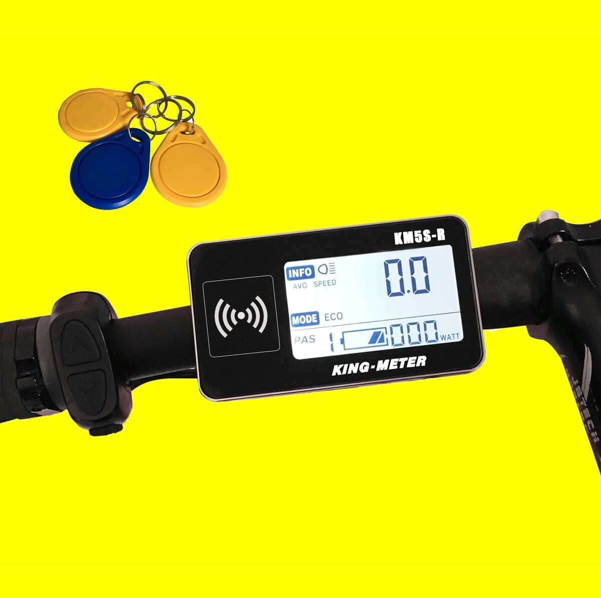
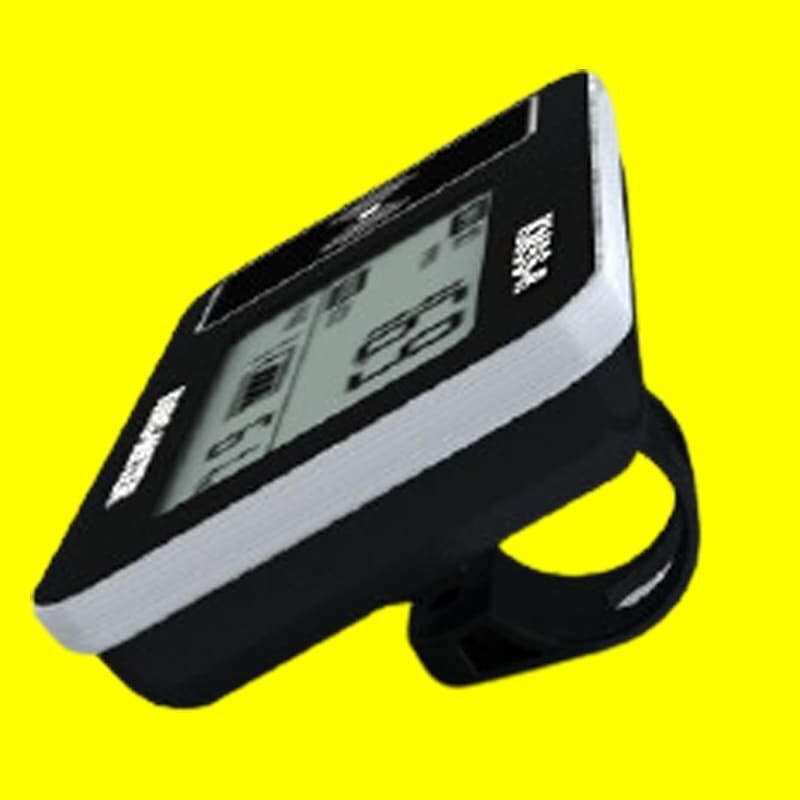
KM5S-R LCD Display
Full function with extra RFID control. RFID key is used to lock and unlock the display, it can also control the whole electric bike system. RFID keys can be customized according to customer requirements.
Additional information
| Size | 88.7mm * 50.3mm * 47.9mm |
|---|---|
| Function | Battery, Headlight, Mile/KM, ODO, PAS Level, Speed, Trip, Trip Time, Walk Assistance, Watt |
| Communication | CAN BUS, LIN, UART |
| Holder | 22.2mm |
| Voltage | 24V, 36V, 48V |
| USB Charging | 5V/500mA |
| Certificate | CE, EN15194:2017, IPX6, RoHS |
| RFID | With |
User Manual_KM5S-R eBike LCD Display
1. About User Manual
Dear users, in order to better operate your electric car, please read the manual of the KM5S-R instrument carefully before use. We will tell you every link of the meter in the simplest language, including the installation and setting of the hardware to the normal use of the meter. At the same time help you solve possible confusion and obstacles.
2. Appearance size
2.1 Main materials and colors for KM5S-R ebike computer
KM5S-R products use PC material. The material of the casing allows normal use at a temperature of -20 ° C to 60 ° C and can guarantee good mechanical properties.
3. Function overview and button definition
3.1 Function Overview
KM5S-R provides you with multiple functions and displays to meet your riding needs. The KM5S-R display shows the below info:
- Battery display
- Remaining mileage display
- Speed display (including real-time speed display, maximum speed display, and average speed display)
- mileage display (including single mileage display and total mileage display)
- Single ride time display
- RFID to secure your ebike
- PAS level display
- Power on/off the backlight
- Error code( for display, controller and battery)
- Multiple setting parameters. Such as backlight, unit.
3.2 Normal display area
3.3 Definition of the button for KM5S-R ebike meter
KM5S-R display has a special N3 button, which could ensure you for use it on both the right and left handlebar.
4. Note to users for KM5S-R ebike meter
Pay attention to safety during use. Do not plug or unplug the instrument while the power is on.
- Try to avoid bumping the meter.
- The film used for the meter is a waterproof film, please do not tear it, so as not to affect the waterproof performance of the meter.
- Regarding the background parameter setting of the meter, please do not change it at will, otherwise, normal riding cannot be guaranteed.
- When the meter cannot be used normally, it should be sent for repair as soon as possible.
5. Installation Notes
Fix the meter on the handlebar and adjust the proper viewing angle. When the electric bicycle is powered off, the connector of the instrument and the connector of the controller are mated to complete the installation.
6. Normal operation
6.1 Power on / off
Short press the MODE key to enter the card swipe interface. Swipe the card within the 30S, the meter starts to work and provides the controller power. More than 30S meter shutdown. In the power-on state, long press the MODE button to turn off the ebike power. In the shutdown state, the meter no longer uses battery power, and the leakage current of the meter is less than 1uA.
If the ebike is not used for more than 5 minutes, the meter will automatically shut down.
6.2 Binding RFID card
The meter displays the card swipe prompt interface. Swipe the main card to enter the main card binding interface. Swipe the card to bind the main card 1, and then bind the secondary card 2 and the secondary card 3 in order. After the binding is successful, the meter will shut down. (For more RFID card display please check the 790-R LED display or T319-R LED Display.)
6.3 Instrument display interface
After the display is turned on, the meter displays the real-time speed by default. Short press the MODE key to switch the displayed information. Displayed in order: real-time speed (unit: Km / h) → average speed of this ride (unit: Km / h) → maximum speed of this ride (unit: Km / h) → accumulated mileage (unit: Km ) → Single mileage (unit: Km) → Single riding time → Real-time speed.
6.4 PAS
The booster logo “PUS” flashes on the display interface.
6.5 USB charging
Plug in a device that requires USB charging when turned off. Turning on the meter at this time will charge the device that needs to be charged. The charging mark “USB” on the display interface flashes. Plug in a device that requires USB charging when the computer is powered on. Press and hold the UP and DOWN buttons and the MODE button to start charging.
6.6 PAS level choosing
Short press the UP or DOWN button to switch the ebike power assist position and change the motor output power. The default output power range of the meter is 0-5, 0 is the lowest power, and 5 is the highest power. The default gear of the meter when it is turned on is 0 gear.
6.7 Power status
When the battery voltage is high, the five segments of the LCD are lit. When the battery is under voltage, the first cell of the battery flashes at a frequency of 1HZ, indicating that the battery is seriously under-voltage and needs to be charged immediately.
6.8 Remaining mileage display
The remaining mileage is displayed as shown below
6.9 Error code display
When the electric control system of the ebike fails, the meter will display the error code cyclically. For a detailed definition of the error code, please refer to Appendix 1.
When the ebike battery system fails, the meter will display the battery error code cyclically. For a detailed definition of the error code, please refer to Appendix 2.
The fault display interface can only be exited when the fault is eliminated and the ebike cannot continue to drive after the fault occurs.
7. User settings
7.1 Preparation before starting
Make sure the connector is docked securely and turn on the ebike.
7.2 General settings
7.2.1 Single mileage and single riding time cleared
In the single-mile or single-ride time display information interface, press and hold the MODE and DOWN keys to clear the single-mile and single-ride time. The single-mile and single-ride time are reset at the same time.
7.3 Parameter settings
In the power-on state, after holding down the UP and DOWN keys simultaneously for 2 seconds, the meter enters the parameter setting.
SET is displayed at the bottom right of the screen, and the number of items is set at the bottom left of the screen.
7.3.1 Backlight brightness
Setting the first item sets the backlight. You can set parameters 1, 2, and 3 to indicate the backlight brightness. 1 is the darkest, 2 is the standard brightness, and 3 is the brightest. The factory default value of the meter is 1. Through UP and DOWN, the backlight brightness parameters can be changed. Press MODE to confirm and enter the metric and inch system setting interface. Press and hold MODE to confirm and exit the setting state.
7.3.2 Unit setting
Setting item 2 sets the metric and imperial system. 1 in English and 0 is metric. Select UP and DOWN to display the corresponding metric and English system. The meter defaults to the metric system. Press and hold MODE to confirm and exit the setting state.
7.4 Exit settings
In the setting state, press MODE (more than 2 seconds) for a long time to confirm saving the current setting and exit the current setting state.
If no operation is performed within 1 minute, the meter will automatically exit the setting state.
8. Frequently Asked Q &A
Q: Why can’t I boot?
Answer: Check if the battery is turned on or the external leakage lead is broken.
Q: What should I do if the meter displays a fault code?
Answer: Go to the repair point of the electric vehicle in time for repair.
9. About barcodes
The instrument bar code is divided into two lines. The first line: KM5S000001. KM5S represents the product name, and 000001 is the product serial number. Second line: 12 06 3 101801. Among them, 1206 represents the instrument’s factory date for the sixth week of 2012, 3 represents the voltage parameters of the instrument (2-24V, 3-36V, 4-48V), 1 represents the sample, 01 represents the instrument hardware version number, and 801 represents the instrument software version number.
10. Quality commitment and warranty coverage
10.1 Warranty Information:
- For any failure caused by the quality of the product under normal use, the company will be responsible for giving a limited warranty during the warranty period.
- The warranty period of the product is within 24 months after the instrument leaves the factory.
10.2 The following conditions are not covered by the warranty
- The shell is opened
- The connector is damaged
- After leaving the instrument, the casing is scratched or damaged.
- The meter lead wire is scratched or broken
- Failure or damage caused by force majeure (such as fire, earthquake, etc.) or natural disasters (such as lightning strikes, etc.)
- The product is out of warranty
11. Connection diagram
Standard connector cable sequence:
| Standard Connector Pins Definition | ||
| Wire | Wire Color | Function |
| 1 | Black(VCC) | The power wire for the display |
| 2 | Brown(K) | – |
| 3 | Orange(GND) | GND |
| 4 | White(CAN-H) | CAN-H for display data |
| 5 | Green(CAN-L) | CAN-L for display data |
Note: The leads of some products use waterproof connectors, and users cannot see the color of the leads in the harness.
12. Version change
The instruction manual of this instrument is the operation manual of the general software version (version 1.0). The version of the instrument software used on some vehicles may be slightly different from this manual, and the actual version used shall prevail.
Appendix 1: Error code for display and controller
| Error Code | Definition |
| 01 | HW break |
| 02 | Batt Over Current |
| 03 | Iph Over Current |
| 04 | Batt Over Voltage |
| 05 | Hall Sensor Error |
| 06 | Turn Block Error |
| 07 | TS Over Limit |
| 08 | TS Under Limit |
| 09 | Throttle Over |
| 10 | Throttle Under |
| 11 | Mosfet Over Temperature |
| 12 | Motor Over Temperature |
| 13 | Under Voltage |
| 14 | Regeneration Error |
| 15 | Turn On While Drive |
| 17 | BMS Time Out |
| 18 | Found BMS |
| 19 | Battery Full |
| 31 | Update FW Error |
| 33 | Display Communication Error |
Note: Here is a more general error code for different e-system for your reference.
Appendix 2: Error code for battery
| Error Code | Definition |
| 01 | Over discharge current (BMSERR_OVER_DC) |
| 02 | Discharge short current (BMSERR_SHORT_DC) |
| 03 | Over voltage (BMSERR_OVER_VOLTAGE) |
| 04 | Under voltage (BMSERR_UNDER_VOLTAGE) |
| 05 | Overcharge current (BMSERR_OVER_CC) |
| 06 | Over temperature (BMSERR_OT) |


