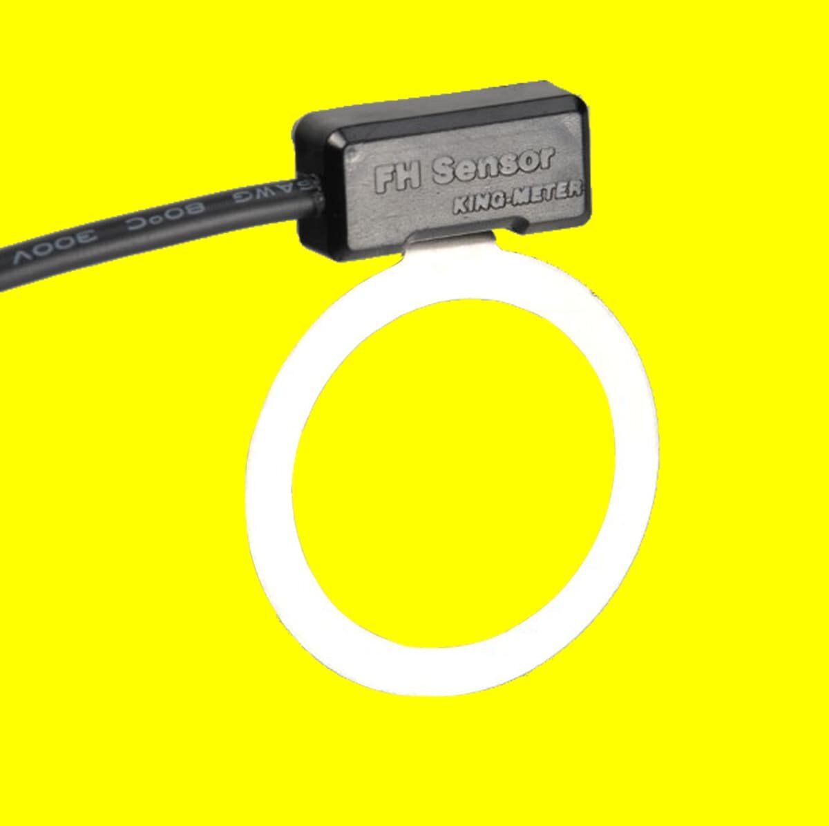
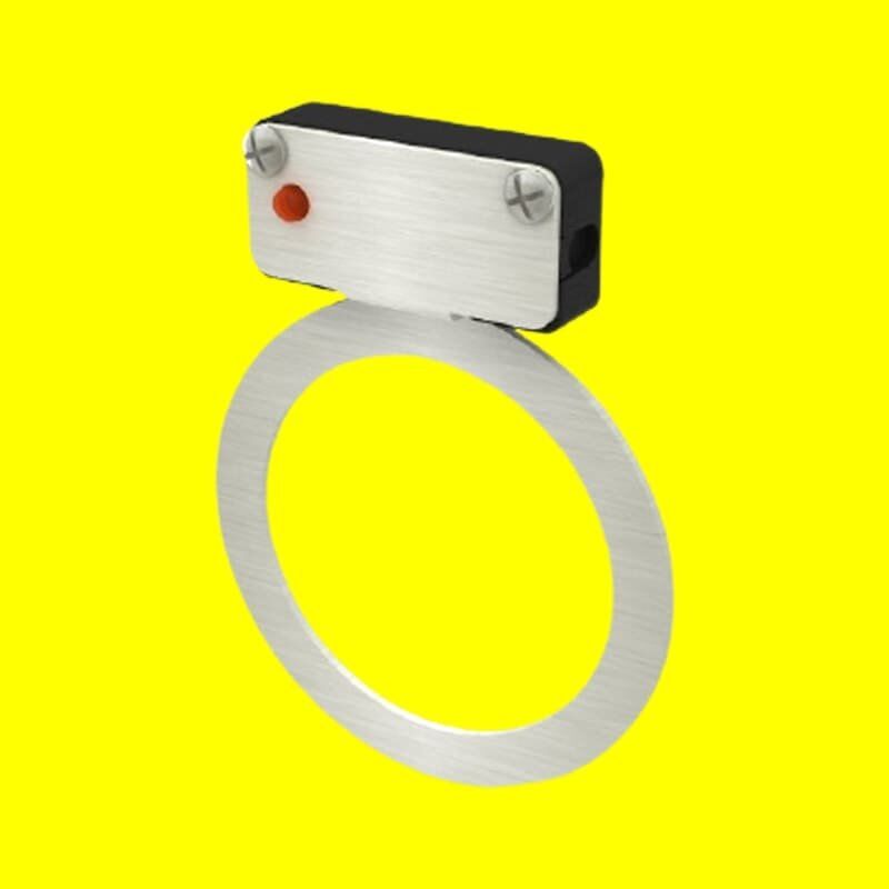
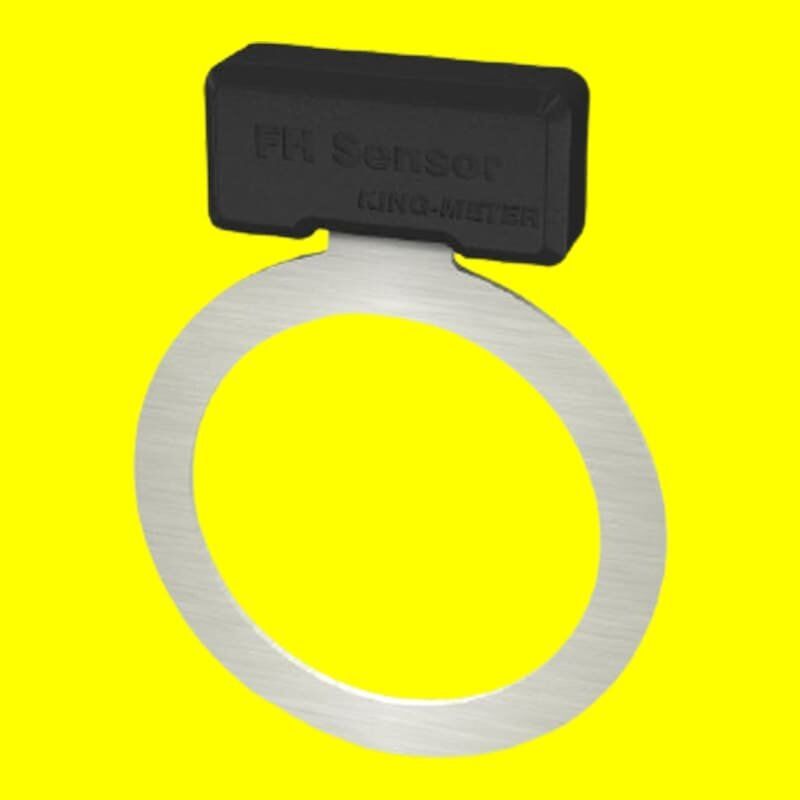
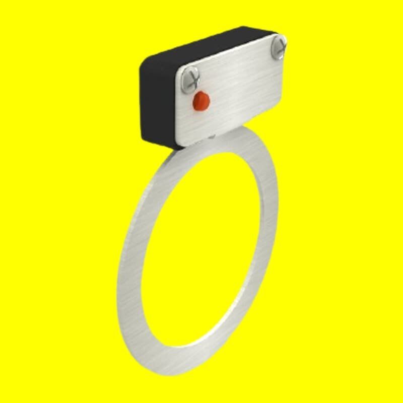
FH Speed Sensor
FH speed sensor contains four hall sensors, when coupled with standard 12 magnet discs, it could provide a 48-pulse output.
Additional information
| Size | 59.5mm * 45mm * 9mm |
|---|---|
| Function | Pedal Assist 48 Signal |
| Voltage | 5V |
| Certificate | CE, EN15194:2017, IPX5, RoHS |
User Manual_FH Sensor
1. Function Introduce
FunctionThe FH 4 Hall sensor is a sensor for electric bicycles. It is divided into left side installation and right side installation. The two sensor programs are different and have the same function. (When ordering, please specify whether it is the left side or right side). Mainly used for the detection of power assist signals. Because it is equipped with a 12 magnet disk, its accuracy is higher than that of a single-Hall sensor using 6 magnet steel, and it is more accurate than the previous double-Hall sensor. It outputs 48 pulse signals, sensing distance. It is farther away than a single Hall sensor using 6 magnets, up to 6.0mm.
Since the four Hall sensor outputs 48 pulse signals, the controller can be more easily matched to achieve the desired effect, and the sensitivity can be improved without malfunction. By default, the ankle rotates forward, the sensor outputs a high pulse signal, and the red LED on the sensor flashes. The ankle turns backward, the sensor continues to output a high potential, and the indicator light is on. This makes it easy for the user to check if the sensor is faulty.
2. Size & Material
FH-SENSOR housing material is PC. The material has good oxidation resistance and aging resistance.
3. Specifications & Reliability
- Voltage:4.5—6V(DC)
- Quiescent Current:<6.5 mA
- Working Current: <7 mA
- Lead tension:>20 N
- Hall response time:<0.001 s
- Response distance:>5 mm
- Hall sensing life:>20 million times
- Dry insulation:>20 MO
- Wet insulation:>2 MO
4. Purchasing Statement
For providing the right goods, please confirm the below details:
- Wire length(Do not include connector)
- FH-SENSOR position on the bike:
- I. Roulette side;
- II. Crank side
- Connector specifications:
- I. Roulette side: Black SM 3A;
- II. Crank side: White SM 3A.(Connector could be customized)
- Pins definition: Red: +5V, Black/Yellow: GND, Blue: Signal


